2 Computing the WCET
Usually, a real-time application is structured as a set of tasks with different periods and deadlines. In OTAWA, we enforce the fact that a task matches a sub-program considered as its entry point. Here, you will learn how to defined a task and how to compute its WCET.
2.1 Basics
To define a task, you have first to select the CFG of its entry point sub-program and to create the task. In our simple example, we consider we have only one task whose entry point is the main function. Select it in the top-left workspace pane and righ-click to get the menu item Add to tasks. This will create an entry in the left-bottom pane you may expand.
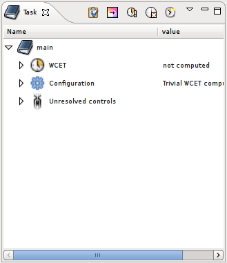
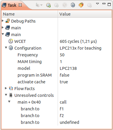
The task contains three sub-items:
WCET – the WCET value in cycles (currently not computed)
Configuration – contains items to configure the computation (see next section)
Unresolved controls – contains items to help OTAWA to resolve complex control flow (see thrid section)
At the top of pane, we have several buttons to control the WCET computation:
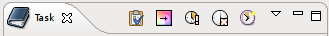
The buttons have, respectively, the functions below:
choose a computation configuration
colorize sources and assembly according the WCET
compute the WCET
delete the currant task
create a new task
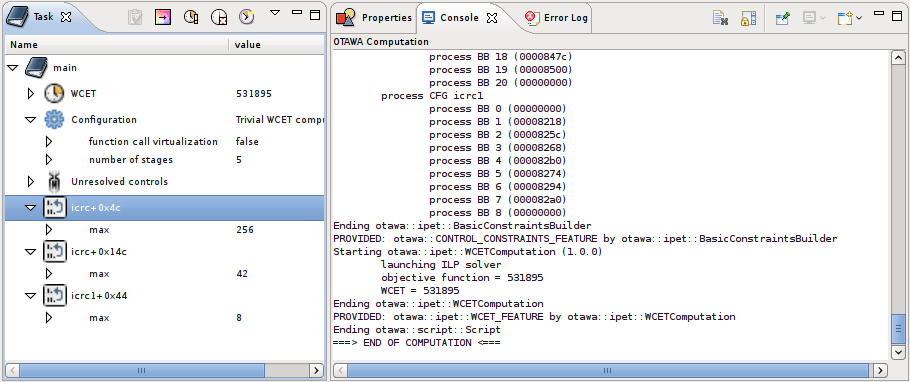
Select the third button to compute the WCET and the console, at the bottom right, will display the different analyses performed by OTAWA to compute the WCET.
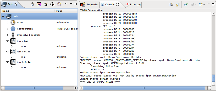
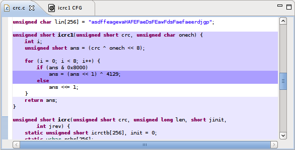
On the left, the WCET value has becomed unbounded. Usually, it means that the WCET have not been computed because bounds for some loops are lacking. This loops appear now in the task pane and you have to get them a maximum value. To find bac which assembly or which source matches a loop, just select them and righ-click to access menu items like Show source > Show C source or Show source > Show assembly.
From the sources, you may find the maximum number of iteration per loop startup. Fill the number as below:
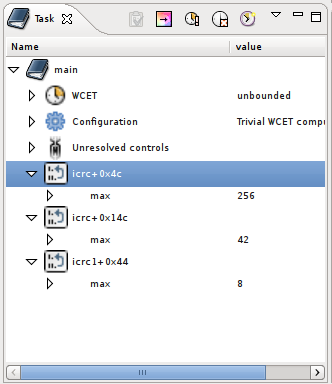
Then, if you relaunch the WCET computation, you will get the WCET in cycles as below:
Once we have got the WCET, the temporal properties of the task can be verified. If the task takes too much time, according to the real-time, a developer might want to modify its task source in order to get shorter WCET. To do this, it may useful to know which part of the code represents the biggest time in the WCET. This is easily achieved by clicking on the second button of the toolbar. Then, all program representation including CFG graphical representation, assembly and sources will be colored according the WCET effect. The darkest is the back, the more important is the impact on the WCET.
Now, you can modify your program and retry to compute the WCET.
2.2 Selecting a computation configuration
One may observe we have not configured the processor before computing the WCET while the execution time of a program depends hardly on the actual model of the used processor. In fact, for the sake of understanding, we have first done our computation with a trivial pseudo-processor accounting for exactly 5 cycles by instruction (no cache, no branch prediction) that makes computation complex.
To select the actual architecture, that is the computation configuration, you have to select the configuration item in the task description that currently displays <code>default</code>. Select the value and click on the appearing right button. This will open a dialog providing a list of possible configuration. By clicking, you will get on the right of the dialog a documentation on the configuration followed by the description of its different parameters.
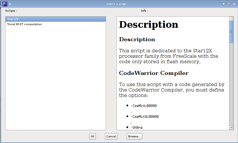
When you choice is done, select the Ok button and the choice will appear in the task configuration item. You may expand it in order to configure the different parameters appearing inside it.
Then, you may relaunch computation in order to get a real value depending on the actual architecture.
2.3 Handling complex control flow
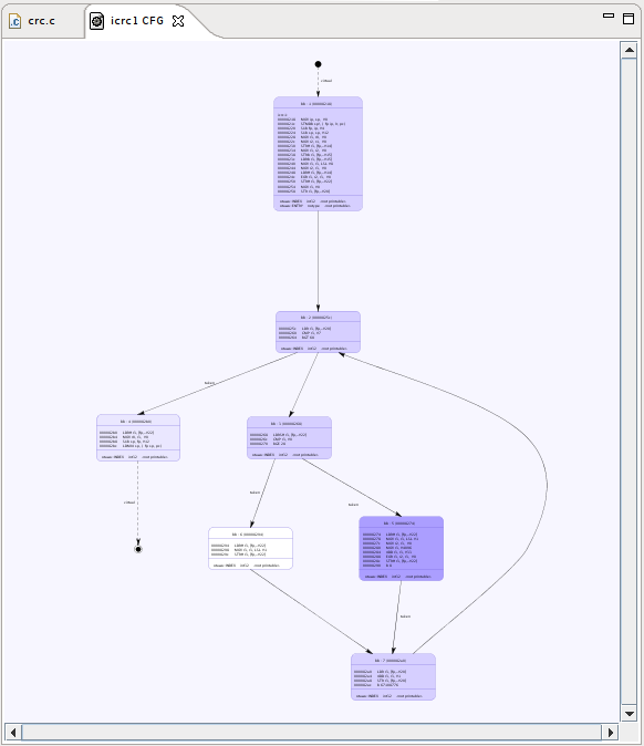
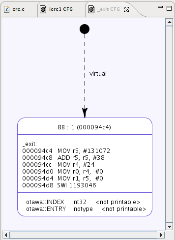
Although OTAWA contains several features to handle complex control flow structures, there are some cases where the user has to help him. To illustrate this, we will compute the WCET of the _exit task. Select its CFG and create the task. You may open the graphical representation of its CFG as below to observe that the _exit unique basic block does not continue with the exiting node. This is due to the presence of the SWI instruction that, on an ARM machine, performs a system call.
Now, the launched WCET computation will failed because the CFG does not contain any solution for a worst case path. Yet, OTAWA will detect the cause of the problem and will propose to the user, in the task pane, some control instructions that has not been solved.

The Unresolved control sub-entry allows to handle by hand a control instruction whose target can not be determined by OTAWA. You have choice between three alternatives:
ignore – ignore the control instruction and continue analysis in sequence
return – consider the control as a return instruction
branch – gives the branch target(s) that have not been resolved by OTAWA
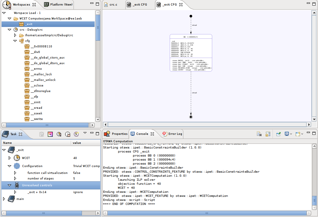
In our example, we choose to ignore the system call and select ignore. Once the WCET computation is relaunched, we get the WCET value.
Notice that unresolved control target usually happens in the following situations:
switch statement translated using indirect branch tables
pointer calls
system calls
2.4 CFG virtualization
In the different given computation configuration, you may be observe a special option called function call computation. According the different WCET computation, this option may be mandatory or let the user choice. Whatever, this option is used to improve the precision of the computation WCET. It consists to replace each function call in a CFG by the copy of the called function CFG. This enlarges the number of basic block to process and, therefore, the price to pay is a bigger computation time.
As a consequence, the result CFG of a task can not be precisely described as a separate set of CFG. To this end, the workspace pane contains an entry called WCET computation that contains the CFG used in the computation. To navigate in the virtualized CFG, just select one of these and right-click to get Open graph option.
To continue with our tutorial, select the main task and select the configuration entry to get the Trivial WCET computation configuration. Set to true the function call virtualization entry and re-launch the WCET computation.
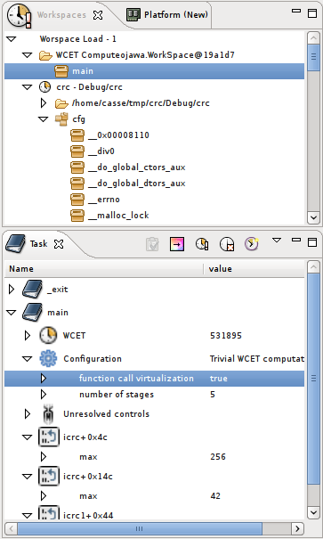
In the WCET computed entry, open the graphical representation.
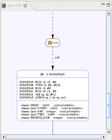
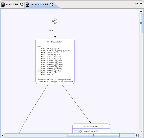
In the CFG graphical representation, the function call are represented as little block containing a box icon. If you double-click on it, the CFG of the called function will open. Note that the same function called at different program point will open different frames becaused they have virtualized and their annotation becomes dependent on the call chain to the function. Another difference lays in the entry and exit blocks. They are now figured with special icons. Double-clicking on them returns back to the caller CFG frame.
Now the tutorial is done, we hope it has been clear enough and makes easier the use of OTAWA. For any question, you may contact me at casse@irit.fr.