Parametric Execution Graph, or parexegraph, is a way to compute execution of code blocks. More...
Classes | |
| class | otawa::ParExeGraph |
| Representation of a parametric execution graph (Parametric Execution Graph). More... | |
| class | otawa::ParExeEdge |
| An edge in a ParExeGraph. More... | |
| class | otawa::ParExeException |
| Exception thrown if there is an error during the build and the computation of. More... | |
| class | otawa::ParExeInst |
| Instruction as presented in the ParExeGraph. More... | |
| class | otawa::ParExeNode |
| A node of the ParExeGraph, that represents the crossing of an instruction inside a microprocessor stage. More... | |
| class | otawa::ParExeSequence |
| A sequence of ParExeInstruction for which a ParExeGraph will be built. More... | |
| class | otawa::ParExeQueue |
| Representation of a hardware instruction queue to be used to build a ParExeGraph. More... | |
| class | otawa::ParExeStage |
| Representation of a pipeline stage to be used to build a ParExeGraph. More... | |
| class | otawa::ParExePipeline |
| Representation of a pipeline (list of stages). More... | |
| class | otawa::ParExeProc |
| Représentation of a processor (to be used to build a ParExeGraph). More... | |
Detailed Description
Parametric Execution Graph, or parexegraph, is a way to compute execution of code blocks.
A parexegraph is a graph whose nodes represents the crossing of an instruction in the microprocessor stage and the edges the time constraints of this crossing.
Principles
This graph is built for a sequence of instructions, whose the execution time is required, and a prefix sequence to take into account the overlapping effect of the pipeline. Depending on the actual microprocessor, the longer is the prefix sequencer, better are the obtained result. The cost of the sequence is obtained after assigning to each node the last starting date and computing the difference between the last stage of the last instruction of the sequence and the last stage of the last instruction of the prefix sequence. The date assignment to each node is performed under the constraint of contention in the use of resources of the microprocessor (stage parallelism, queues, functional units, etc). Below is an example of such a parametric execution graph:
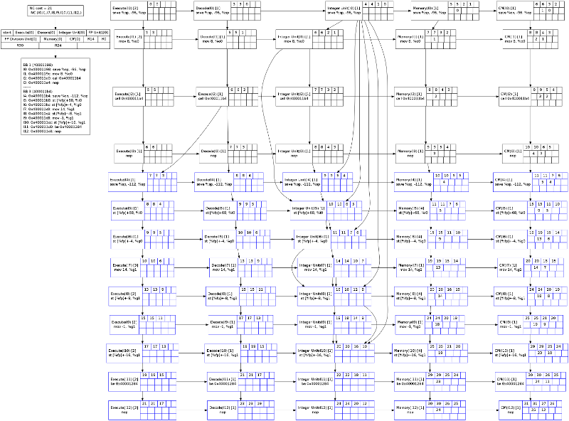
As a basis, the pipeline microprocessor is taken from the platform processor description (possibly coming from an external XML file or specially built). As the model used to describe microprocessor is relatively simple and does not allow to describe any type of microprocessor, the use of parexegraph may require to customize the way the graph is built.
Customization
Basically, an execution graph is represented by a ParExeGraph class whose provide also the computation of the cost of a sequence. To compute the cost fore each block a program, for example basic block, a dedicated processor like GraphBBTime has to be invoked. As the execution graphs needs to be customized, this analyzer takes a generic parameter defining the actual execution graph to use. To perform the computation in the standard way, you have either to implemened GraphBBTime with ParExeGraph as the parametric argument:
Or to use an analyzer as BasicGraphBBTime that already provides such an implementation.
Yet, if your hardware does not fits the standard OTAWA processor model, you may to customize the way the graphs are built.
First, build a model as close as possible in the processor model of OTAWA and use a way to pass it to pass it to the WCET building system. This may be done using the configuration properties (PROCESSOR_PATH, PROCESSOR_ELEMENT or PROCESSOR) or using an OTAWA script (in the platform section).
Then, you provide your own parametric execution graph implementation by overloading the ParExeGraph class and pass as parametric argument to GraphBBTime. To build the graph, the function ParExeGraph::build() is called that, in turn, calls the following methods:
- void ParExeGraph::createNodes(void) – creates the nodes of the graph,
- void ParExeGraph::addEdgesForPipelineOrder(void) – add edges to follow stage pipeline order,
- void ParExeGraph::addEdgesForFetch(void) – add edges to support fetching effects (according to the instruction cache as a default),
- void ParExeGraph::addEdgesForProgramOrder(elm::genstruct::SLList<ParExeStage *> *list_of_stages) – add edges to represent program order,
- void ParExeGraph::addEdgesForMemoryOrder(void) – add edges to support memory access order,
- void ParExeGraph::addEdgesForDataDependencies(void) – add edges for data dependencies,
- void ParExeGraph::addEdgesForQueues(void) – add edges to represent access to queues.
All these methods are virtual and can be overridden to implements the specific behaviour of your hardware.
Structure
A parametric execution graph, ParExeGraph, is made of nodes, ParExeNode, and of edges, ParExeEdge linking two nodes. An edge may be solid, ParExeEdge::SLASHED, representing a possible startup at the same time, or ParExeEdge::SOLID, representing a sequence in the startup (at least one cycle). The time passed in a node or on a edge may be customized. A node is the join of an instruction, ParExeInst, executed on a particular pipeline stage,
- ParExeStage.
Basically,the parametric execution graph is generated from a processor description, ParExeProc, whose most interesting paer is the ParExePipeline that contains two collections:
- a collection of queues, ParExeQueue, representing the queues inside the processor,
- a list of stages, ParExeStage, representing the stages in order in the pipeline.
In turn, if the ParExeStage is an execution stage, it is composed of ParExePipeline that contains functional units represented by ParExeStage.
To build the graph, a user has to pass ParExeSequence, made of ParExeInst, that represents, in order, the concatenation of prefix and processed sequences. The ParExeInst are marked according to their ownership to the prefix or the processed sequence (type ParExeInst::code_part_t).